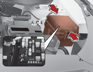
Replacing engine compartment fuse

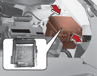
After checking the fuse panel in the engine compartment, securely install the fuse panel cover through the audible clicking sound.
If not, electrical failures may occur from water contact.
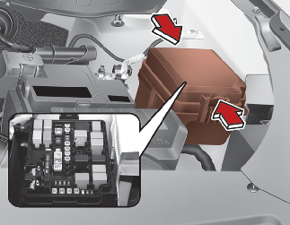
Main fuse (Multi fuse)
If the multi fuse is blown, it must be removed as follows:

If the multi fuse is blown, consult a professional workshop. Kia recommends to consult an authorized Kia dealer/service partner.
Driver's side fuse panel
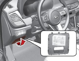
Not all fuse panel descriptions in this manual may be applicable to your vehicle. It is accurate at the time of printing. When you inspect the fuse panel in your vehicle, refer to the fuse panel label on the inside of the fuse cover. This diagram will provide you with the specific information for your vehicles.
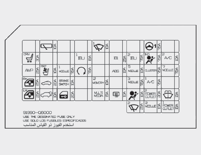
Refer to the following table for a description of the fuse.
|
Fuse Name |
Symbol |
Fuse rating |
Circuit Protected |
|---|---|---|---|
|
P/SEAT (DRV) |
 |
30 A |
Driver Seat Manual Switch |
|
AMP |
 |
25 A |
AMP (Amplifier) |
|
P/WDW RH |
 |
25 A |
Power Window Relay RH, Driver Safety Power Window Module |
|
P/WDW LH |
 |
25 A |
Power Window Relay LH, Driver Safety Power Window Module |
|
WIPER RR |
 |
10 A |
Engine Room Block (Rear Wiper Relay), Rear Wiper Motor |
|
SEAT VENT FRT |
 |
10 A |
Front Air Ventilation Seat Control Module |
|
SUNROOF |
 |
20 A |
Sunroof Unit |
|
TAIL GATE OPEN |
 |
10 A |
Tail Gate Relay |
|
MODULE 1 |
 |
7.5 A |
Hazard Switch, Data Link Connector |
|
BRAKE SWITCH |
 |
10 A |
Stop Lamp Switch, IBU (Integrated Body Control Unit) |
|
DOOR LOCK |
 |
20 A |
Door Lock Relay, Door Unlock Relay |
|
IBU1 |
 |
15 A |
IBU (Integrated Body Control Unit) |
|
START |
 |
7.5 A |
[Manual Transmission & Without Smart Key] Ignition Lock & Clutch Switch [Manual Transmission & With Smart Key] Engine Room Block (Start Relay), IBU (Integrated Body Control Unit), ECM (Engine Control Module), PCM (Power train Control Module) [Auto Transmission] Transmission Range Switch |
|
WIPER FRT1 |
 |
10 A |
IBU (Integrated Body Control Unit), ECM (Engine Control Module)/PCM (Power train Control Module) |
|
MEMORY 2 |
 |
10 A |
ICM (Integrated Circuit Module) Relay Box (Outside Mirror Folding/Unfolding Relay), Instrument Cluster, Air Conditioner Control Module, Security Indicator, Head-Up Display |
|
MULTI MEDIA |
 |
15 A |
Audio., Audio/Video & Navigation Head Unit |
|
IG1 |
 |
25 A |
Engine Room Block (Fuse - F33, F34, F35) |
|
ABS |
 |
10 A |
ESP (Electronic Stability Program) Control Module, Data Link Connector |
|
REAR HAETED |
 |
10 A |
ECM (Engine Control Module), PCM (Power train Control Module), Air Conditioner Control Module |
|
IBU2 |
 |
7.5 A |
IBU (Integrated Body Control Unit) |
|
MODULE 5 |
 |
10 A |
Electro Chromic Mirror, IBU (Integrated Body Control Unit), Front Wireless Charger, Auto Transmission Shift Lever Indicator, Driver Console Switch, Audio, Audio/Video & Navigation Head Unit, Air Conditioner Control Module, Crash Pad Switch, AMP (Amplifier), Front Air Ventilation Seat Control Module |
|
MODULE 3 |
 |
7.5 A |
Stop Lamp Switch, Auto Transmission Shift Lever |
|
AIR BAG |
 |
10 A |
SRS (Supplemental Restraint System) Control Module |
|
FRT WIPER2 |
 |
25 A |
Engine Room Block (Wiper 1 Relay), Front Wiper Motor |
|
MDPS |
 |
7.5 A |
MDPS (Motor Driven Power Steering) Unit |
|
A/BAG IND |
 |
7.5 A |
Cluster |
|
CLUSTER |
 |
7.5 A |
Instrument Cluster, Head-Up Display |
|
A/C1 |
 |
7.5 A |
Engine Room Block (Blower Relay), Air Conditioner Control Module |
|
POWER OUTLET2 |
 |
20 A |
Front Power Outlet #1 |
|
MODULE 2 |
 |
10 A |
USB Charger, IBU (Integrated Body Control Unit), Audio, Surround View Monitor, Audio/Video & Navigation Head Unit, AMP (Amplifier), Power Outside Mirror Switch |
|
A/C2 |
 |
10 A |
Air Conditioner Control Module |
|
MODULE 7 |
 |
7.5 A |
Head Lamp LH/RH, IBU (Integrated Body Control Unit), Crash Pad Switch, Front Air Ventilation Seat Control Module |
|
WASHER |
 |
15 A |
Multifunction Switch |
|
POWER OUTLET1 |
 |
15 A |
Front Power Outlet #1 |
Engine compartment fuse panel
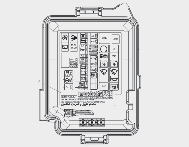
Refer to the following table for a description of the fuse.
|
Fuse Name |
Symbol |
Fuse rating |
Circuit Protected |
|---|---|---|---|
|
ALT |
 |
150 A |
[ALL] Alternator, Rear Defogger Relay, ESP (Electronic Stability Program) Control Module, ESP (Electronic Stability Program) Control Module, Blower Relay [Kappa 1.4 T-GDI] Cooling Fan Motor [U2 1.5 TCI] Glow Relay Unit |
|
MDPS1 |
 |
80 A |
MDPS (Motor Driven Power Steering) Unit |
|
C/FAN BLDC |
 |
80 A |
[Kappa 1.4 T-GDI] Cooling Fan Motor |
|
GLOW |
 |
[U2 1.5 TCI] Glow Relay Unit |
|
|
RR HTD |
 |
30 A |
Rear Defogger Relay |
|
ABS1 |
 |
40 A |
ESP (Electronic Stability Program) Control Module |
|
ABS2 |
 |
30 A |
ESP (Electronic Stability Program) Control Module |
|
BLOWER |
 |
40 A |
Blower Relay |
|
ECU4 |
 |
20 A |
ECM (Engine Control Module), PCM (Power train Control Module) |
|
SENSOR 1 |
 |
10 A |
[ALL] Fuel Pump Relay [U2 1.5 TCI] Inlet Metering Unit |
|
SENSOR 2 |
 |
10 A |
[ALL] Oxygen Sensor (Up/Down), Oil Control Valve #1/#2, Variable Intake Solenoid Valve, Purge Control Solenoid Valve [Kappa 1.4 T-GDI] Air Conditioner Relay [Gamma 1.6 MPI] Cooling Fan 2 Relay, Air Conditioner Relay, Cooling Fan 1 Relay [U2 1.5 TCI] Cooling Fan 2 Relay, Air Conditioner Relay, Cooling Fan 1 Relay |
|
SGA |
 |
40 A |
[Kappa 1.4 T-GDI] Smart Gear Actuator |
|
FULL HTR |
 |
30 A |
[U2 1.5 TCI] Fuel Heater Relay |
|
ECU1 |
 |
30 A |
Main Relay |
|
DCT1 |
 |
40 A |
TCM (Transmission Control Module) |
|
DCT2 |
 |
40 A |
TCM (Transmission Control Module) |
|
DCT3 |
 |
15 A |
TCM (Transmission Control Module) |
|
ECU2 |
 |
15 A |
ECM (Engine Control Module), PCM (Power train Control Module) |
|
ECU5 |
 |
15 A |
ECM (Engine Control Module), PCM (Power train Control Module) |
|
TCU1 |
 |
25 A |
ECM (Engine Control Module), PCM (Power train Control Module), TCM (Transmission Control Module) |
|
IG2 |
 |
40 A |
Start Relay, IG2 Relay, Ignition Switch |
|
IG1 |
 |
40 A |
ACC Relay, IG1 Relay, Ignition Switch |
|
B+1 |
 |
60 A |
ICU Junction Block (Long Term Load Auto Cut Relay, Fuse - Hazard Switch, Data Link Connector, Stop Lamp Switch, IBU (Integrated Body Control Unit)) |
|
B+2 |
 |
50 A |
ICU Junction Block (IPS4, IPS5, IPS6, IPS8, IPS9, IPS11, IPS12, IPS17) |
|
B+3 |
 |
60 A |
ICU Junction Block (IPS1, IPS2, IPS3, IPS7, IPS10, IPS13, IPS16, IPS18, IPS20) |
|
FUEL PUMP |
 |
20 A |
Fuel Pump Relay |
|
VACUUM PUMP1 |
 |
20 A |
[Kappa 1.4 T-GDI] Vacuum Pump |
|
AMS |
 |
10 A |
[U2 1.5 TCI] Battery Sensor |
|
HORN |
 |
15 A |
Horn Relay, B/A Horn Relay |
|
A/C |
 |
10 A |
Air Conditioner Relay |
|
B+4 |
 |
50 A |
ICU Junction Block (Fuse - Driver Seat Manual Switch, AMP (Amplifier), Power Window Relay RH, Driver Safety Power Window Module, Power Window Relay LH, Driver Safety Power Window Module, Front Air Ventilation Seat Control Module, Sunroof Unit, Tail Gate Relay) |
|
C/FAN |
 |
40 A |
[Gamma 1.6 MPI, Kappa 1.4 T-GDI] Cooling Fan 2 Relay, Cooling Fan 1 Relay |
|
C/FAN |
|
50 A |
[U2 1.5 TCI] Cooling Fan 2 Relay, Cooling Fan 1 Relay |
|
ECU6 |
 |
10 A |
ECM (Engine Control Module), PCM (Power train Control Module) |
|
VACUUM PUMP2 |
 |
10 A |
[Kappa 1.4 T-GDI] Vacuum Pump |
|
SENSOR 4 |
 |
10 A |
Glow Relay Unit, Fuel Filter Warning Sensor |
|
TCU2 |
 |
10 A |
[Manual Transmission] Speed Sensor [Auto Transmission] Transmission Range Switch, TCM (Transmission Control Module) |
|
ECU3 |
 |
20 A |
ECM (Engine Control Module), PCM (Power train Control Module) |
|
INJECTOR |
 |
15 A |
[Gamma 1.6 MPI] Injector #1/#2/#3/#4 |
|
SENSOR 3 |
 |
10 A |
[ALL] Mass Air Flow Sensor, PM Sensor, Electronic VGT (Variable Geometry Turbocharger) Actuator [Kappa 1.4 T-GDI] Cooling Fan Motor [U2 1.5 TCI] EGR Cooling Bypass Solenoid Valve |
|
IGN COIL |
 |
20 A |
Ignition Coil #1/#2/#3/#4, Condenser |
Refer to the following table for the relay type.
|
Relay Name |
Symbol |
Type |
|---|---|---|
|
Main Relay |
 |
MINI |
|
Start Relay |
 |
MICRO |
|
Fuel Heater Relay |
 |
MICRO |
|
Cooling Fan 2 Relay |
 |
MICRO |
|
Wiper 1 Relay |
 |
MICRO |
|
A/C Relay |
 |
MICRO |
|
ACC Relay |
 |
MICRO |
|
IG1 Relay |
 |
MICRO |
|
IG2 Relay |
 |
MICRO |
|
Cooling Fan 1 Relay |
 |
MICRO |
|
Wiper 2 Relay |
 |
MICRO |
|
Horn Relay |
 |
MICRO |
|
Rear Defogger Relay |
 |
MICRO |
|
Blower Relay |
 |
MICRO |
|
Rear Wiper Relay |
 |
MICRO |
|
B/A Horn Relay |
 |
MICRO |
|
Fuel Pump Relay |
 |
MICRO |