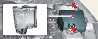
Replacing engine compartment fuse
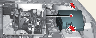

After checking the fuse panel in the engine compartment, securely install the fuse panel cover through the audible clicking sound.
If not, electrical failures may occur from water contact.
Main fuse (Multi fuse)
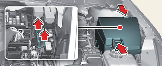
If the multi fuse is blown, it must be removed as follows:

If the multi fuse is blown, consult a professional workshop. Kia recommends to consult an authorized Kia dealer/service partner.
Driver's side fuse panel
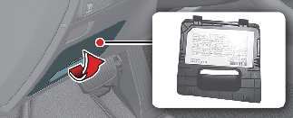
Not all fuse panel descriptions in this manual may be applicable to your vehicle. It is accurate at the time of printing. When you inspect the fuse panel in your vehicle, refer to the fuse panel label on the inside of the fuse cover. This diagram will provide you with the specific information for your vehicles.
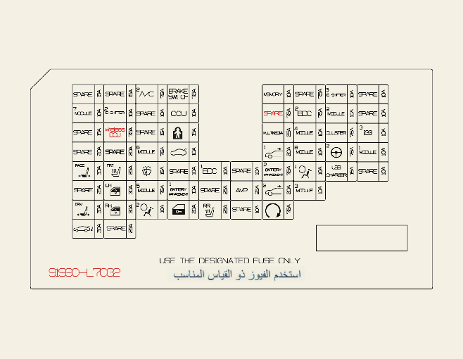
Refer to the following table for a description of the fuse.
|
Fuse Name |
Symbol |
Fuse rating |
Circuit Protected |
|---|---|---|---|
|
S/HEATER (FRT) |
 |
25 A |
Front Seat Warmer Control Module, Front Air Ventilation Seat Control Module |
|
TRUNK |
 |
10 A |
Trunk Lid Relay |
|
DOOR LOCK |
 |
20 A |
Door Lock Relay, Door Unlock Relay |
|
MODULE1 |
 |
7.5 A |
Front Console Switch #1, Driver/Passenger Smart Key Outside Handle |
|
CHILD LOCK |
 |
15 A |
Rear Child Lock Relay, Rear Child Unlock Relay |
|
MODULE3 |
 |
10 A |
Hazard Switch, Front Mood Lamp Unit, Data Link Connector, Passenger Seat Relax Unit, Driver Door Module, Driver/Passenger Door Mood Lamp, Front Mood Lamp Right Handle side |
|
S/HEATER (RR) |
 |
25 A |
Rear Seat Warmer Control Module |
|
P/SEAT (PASS) |
 |
30 A |
Passenger Seat Manual Switch, Passenger Seat Relax Unit |
|
MODULE6 |
 |
7.5 A |
Driver Door Module |
|
P/WINDOW (RH) |
 |
30 A |
Passenger Safety Power Window Module, Passenger Power Window Switch, Rear Power Window Switch Right Handle side |
|
P/SEAT (DRV) |
 |
30 A |
Driver Seat Manual Switch, Driver IMS Module |
|
BDC1 |
 |
10 A |
IBU (Integrated Body Control Unit) |
|
AMP |
 |
25 A |
AMP (Amplifier) |
|
P/WINDOW (LH) |
 |
30 A |
Driver Safety Power Window Module, Rear Power Window switch Left Handle side |
|
BRAKE SWITCH |
 |
10 A |
IBU (Integrated Body Control Unit), Stop Lamp Switch |
|
SUNROOF2 |
 |
20 A |
Sunroof Controller (Blind Motor) |
|
AIR BAG2 |
 |
10 A |
SRS (Supplemental Restraint System) Control Module |
|
AIR BAG1 |
 |
10 A |
SRS (Supplemental Restraint System) Control Module |
|
E-SHIFTER3 |
 |
10 A |
SCU, Electronic Shift Dial (SBW) |
|
MEMORY |
 |
10 A |
Driver IMS Module, Rain Sensor, Head-Up Display, Instrument Cluster, Air Conditioner Control Module, Air Conditioner Switch, Driver/Passenger Power Outside Mirror |
|
MULTI MEDIA |
 |
25 A |
Audio, Audio/Video & Navigation Head Unit |
|
SUNROOF1 |
 |
20 A |
Sunroof Controller (Glass Motor) |
|
POWER TRUNK |
|
30 A |
Power Trunk Lid |
|
WIRELESS DCU |
 |
7.5 A |
Data Connectivity Unit |
|
CCU |
 |
10 A |
Central Communication Unit |
|
BATTERY MANAGEMENT1 |
|
10 A |
Battery Management System |
|
BATTERY MANAGEMENT2 |
|
7.5 A |
Battery Management System |
|
MODULE7 |
 |
10 A |
Front Console Switch #1/#2, Front View Camera, Crash Pad Switch, IBU (Integrated Body Control Unit), ADAS Parking ECU |
|
MODULE5 |
 |
7.5 A |
Stop Lamp Switch, Electronic Shift Dial (SBW) |
|
MODULE8 |
 |
10 A |
Front Seat Warmer Control Module, Front Air Ventilation Seat Control Module, Passenger Seat Relax Unit, Rear Seat Warmer Control Module, AMP (Amplifier), Driver IMS Module, Data Link Connector, Audio, Audio/Video & Navigation Head Unit, Head Lamp Left Handle side/Right Handle side, Surround View Monitor Unit, Air Conditioner Control Module, Air Conditioner Switch, Front Wireless Charger, Electro Chromic Mirror, Overhead Console Lamp (Lamp), Crash Pad Switch |
|
E-SHIFTER2 |
 |
10 A |
SCU |
|
MODULE2 |
 |
10 A |
Cooling Fan Motor, Passenger Seat Relax Unit, Rear Seat Warmer Control Module, ADAS Parking ECU, Front Seat Warmer Control Module, Front Air Ventilation Seat Control Module |
|
MDPS |
 |
7.5 A |
MDPS (Motor Driven Power Steering) Unit*1 |
|
A/C2 |
 |
7.5 A |
Air Conditioner Control Module, Air Conditioner Switch, Engine Room Junction Block (Blower Relay, PTC Heater1 Relay, PTC Heater2 Relay), Electronic Air Conditioner Compressor |
|
MODULE4 |
 |
10 A |
Rear USB Charger, IBU (Integrated Body Control Unit), Audio, Audio/Video & Navigation Head Unit, Surround View Monitor Unit, AMP (Amplifier), BMS (Battery Management System) Control Module, ADAS Parking ECU, PCB Block (Power Outlet Relay) |
|
CLUSTER |
 |
7.5 A |
Instrument Cluster, Head-Up Display |
|
WASHER |
 |
15 A |
Multifunction Switch |
|
START |
 |
7.5 A |
IBU (Integrated Body Control Unit), HPCU (Hybrid Power Control Unit) |
|
IBU2 |
 |
7.5 A |
IBU (Integrated Body Control Unit) |
|
USB CHARGER |
 |
15 A |
Front USB Charger, Rear USB Charger |
|
IG3 3 |
 |
10 A |
CCU (Central Communication Unit) |


* 1. MDPS(Motor Driven Power Steering) is the same as EPS(Electric Power Steering).
Engine compartment fuse panel
Not all fuse panel descriptions in this manual may be applicable to your vehicle. It is accurate at the time of printing. When you inspect the fuse panel in your vehicle, refer to the fuse panel label on the inside of the fuse cover. This diagram will provide you with the specific information for your vehicles.
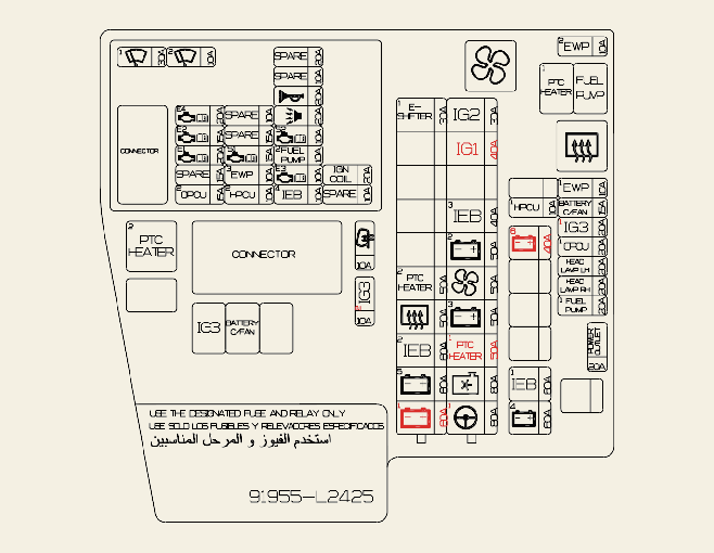
Refer to the following table for a description of the fuse.
|
Fuse Name |
Symbol |
Fuse rating |
Circuit Protected |
|---|---|---|---|
|
E-SHIFTER1 |
|
30 A |
SCU |
|
IG1 |
 |
40 A |
PCB Block (ACC Relay, IG1 Relay) |
|
PTC HEATER2 |
 |
50 A |
PTC Heater2 Relay |
|
REAR DEFOGGER |
 |
50 A |
Rear Defogger Relay |
|
IEB2 |
 |
60 A |
Integrated Electric Brake Module |
|
B+5 |
 |
60 A |
PCB Block (Main Relay, Fuse - WIPER1, ECU4, ECU2, HORN, B/A HORN) |
|
PTC HEATER1 |
 |
50 A |
PTC Heater1 Relay |
|
IG2 |
 |
30 A |
PCB Block (IG2 Relay) |
|
IEB3 |
 |
40 A |
Integrated Electric Brake Module |
|
B+2 |
 |
50 A |
ICU Junction Block (Fuse - IBU1, AMP, IPS1, 1PS2, IPS3, IPS4, IPS10) |
|
BLOWER |
 |
50 A |
Blower Relay |
|
B+3 |
 |
50 A |
ICU Junction Block (IPS5, IPS6, IPS7, IPS8, IPS9, IPS11) |
|
B+1 |
 |
60 A |
ICU Junction Block (Fuse - MODULE1, CHILD LOCK, S/HEATER (RR), P/SEAT (PASS), SAFETY P/WINDOW (RH), P/SEAT (DRV), SAFETY P/WINDOW (LH)) |
|
COOLING FAN |
 |
80 A |
Cooling Fan Motor |
|
MDPS1 |
 |
80 A |
MDPS (Motor Driven Power Steering) Unit*1 |
|
HEV ECU1 |
 |
10 A |
HPCU (Hybrid Power Control Unit) |
|
POWER OUTLET |
 |
20 A |
PCB Block (Power Outlet Relay) |
|
IEB1 |
 |
60 A |
Integrated Electric Brake Module |
|
B+4 |
 |
60 A |
ICU Junction Block (Long Term Load Latch Relay, Fuse - S/HEATER (FRT), TRUNK, DOOR LOCK, MODULE3, BRAKE SWITCH, SUNROOF2, AIR BAG2, E-SHIFTER1, SUNROOF1) |
|
EWP1 |
 |
10 A |
Electronic Water Pump (Engine) |
|
BATTERY C/FAN |
 |
15 A |
Battery C/Fan Relay |
|
IG3 1 |
 |
20 A |
IG3 Relay |
|
OPCU1 |
 |
20 A |
OPU |
|
FUEL PUMP |
 |
20 A |
Fuel Pump Relay |
|
EWP2 |
 |
10 A |
Electronic Water Pump (HEV), Battery C/FAN Relay, ICU Junction Block (IPS Control Module) |
|
MIRROR HEATED |
 |
10 A |
Driver/Passenger Power Outside Mirror, Air Conditioner Switch |
|
IG3 2 |
 |
10 A |
HPCU (Hybrid Power Control Unit) |
|
HEAD LAMP LH |
 |
20 A |
HEAD LAMP LH |
|
HEAD LAMP RH |
 |
20 A |
HEAD LAMP RH |

* 1. MDPS(Motor Driven Power Steering) is the same as EPS(Electric Power Steering).
|
Fuse Name |
Symbol |
Fuse rating |
Circuit Protected |
|---|---|---|---|
|
WIPER1 |
 |
30 A |
Wiper Power Relay |
|
WIPER2 |
 |
10 A |
IBU (Integrated Body Control Unit) |
|
ECU4 |
 |
20 A |
PCM (Power train Control Module) |
|
ECU2 |
 |
15 A |
PCM (Power train Control Module) |
|
ECU1 |
 |
20 A |
PCM (Power train Control Module) |
|
OPCU2 |
 |
15 A |
OPU |
|
SENSOR1 |
 |
15 A |
Oxygen Sensor (Up/Down) |
|
HEV ECU2 |
|
10 A |
HPCU (Hybrid Power Control Unit) |
|
HORN |
 |
20 A |
Horn Relay |
|
B/A HORN |
 |
20 A |
B/A Horn Relay |
|
SENSOR2 |
 |
10 A |
Oil Control Valve (Intake), Oil Control Valve (Exhaust), Purge Control Solenoid Valve, Oil Pressure Control Valve |
|
FUEL PUMP2 |
 |
10 A |
Engine Room Junction Block (Fuel Pump Relay) |
|
ECU3 |
 |
10 A |
PCM (Power train Control Module) |
|
IEB4 |
 |
10 A |
Integrated Electric Brake Module |
|
IGN COIL |
 |
20 A |
IGNITION COIL #1#2/#3/#4 |
Refer to the following table for the relay type.
|
Relay Name |
Type |
|---|---|
|
Blower Relay |
MINI |
|
PTC Heater1 Relay |
MICRO |
|
Rear Heated Relay |
MINI |
|
PTC Heater2 Relay |
MINI |
|
Fuel Pump Relay |
MICRO |
|
Battery C/Fan Relay |
MICRO |
|
IG3 Relay |
MICRO |