Fuse/relay panel description
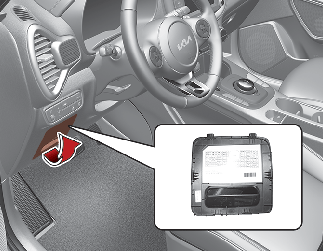
Driver's side fuse panel

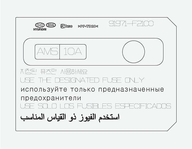
Not all fuse panel descriptions in this manual may be applicable to your vehicle. It is accurate at the time of printing. When you inspect the fuse panel in your vehicle, refer to the fuse panel label on the inside of the fuse cover. This diagram will provide you with the specific information for your vehicles.
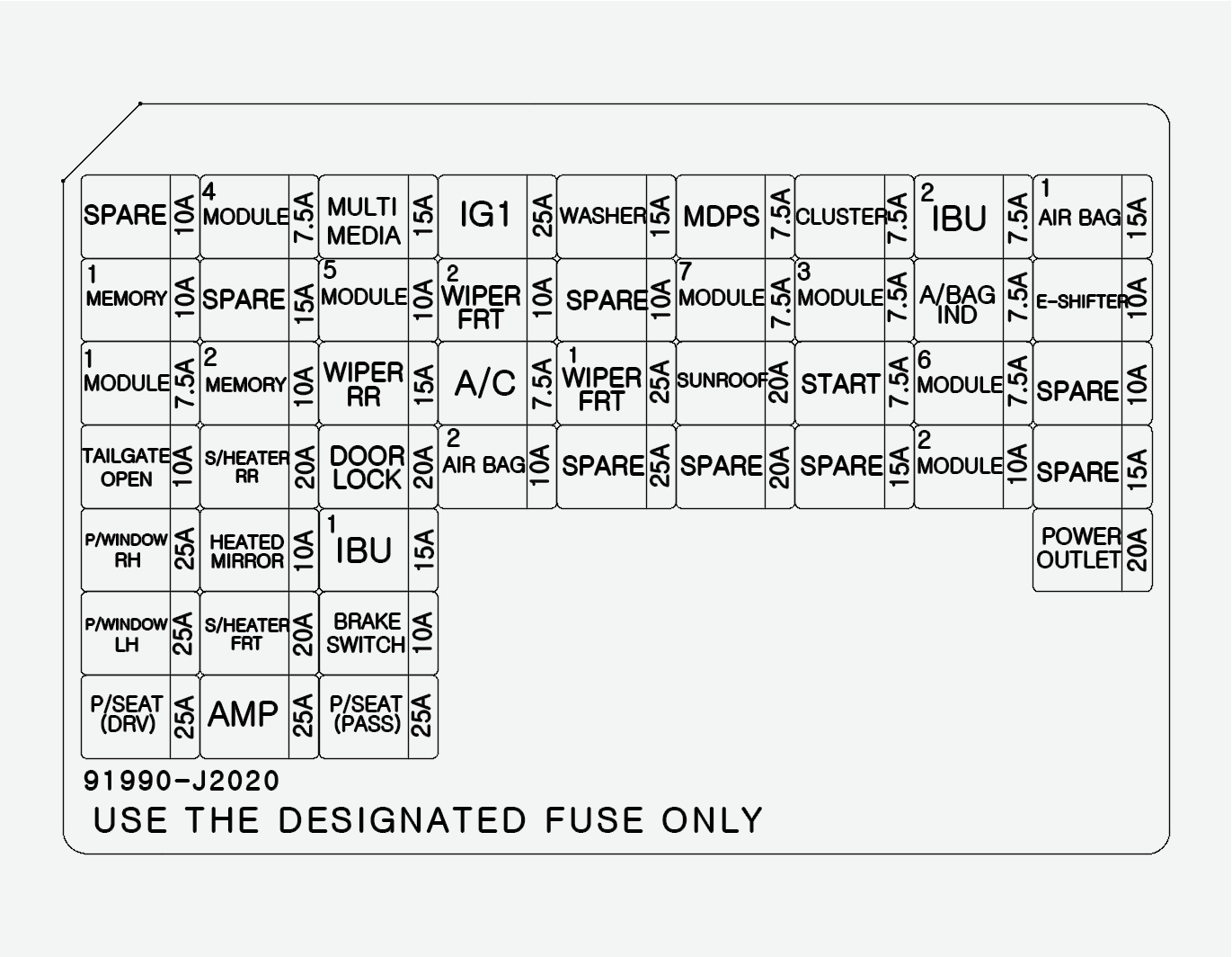
Refer to the following table for a description of the fuse.
|
Fuse Name |
Fuse rating |
Circuit Protected |
|---|---|---|
|
POWER OUTLET |
20 A |
Front Power Outlet |
|
MODULE2 |
10 A |
E/R Junction Block (Power Outlet Relay), Audio, Rear USB Charger, Wireless Charger, Sound Mood Amplifier, Amplifier, Driver/Passenger Door Mood Range Amplifier, Power Outside Mirror Switch, A/V & Navigation Head Unit, IBU (Integrated Body Control Unit) |
|
HEATED MIRROR |
10 A |
Driver/Passenger Power Outside Mirror, Air Conditioner Control Module |
|
IG1 |
25 A |
PCB Block (Fuse - IEB2, IEB3) |
|
AIR BAG1 |
15 A |
Occupant Detection Sensor, SRS (Supplemental Restraint System) Control Module |
|
A/BAG IND |
7.5 A |
Instrument Cluster, Air Conditioner Control Module |
|
IBU2 |
7.5 A |
IBU (Integrated Body Control Unit) |
|
CLUSTER |
7.5 A |
HUD, Instrument Cluster |
|
MDPS *1 |
7.5 A |
MDPS (Motor Driven Power Steering) Unit |
|
MODULE3 |
7.5 A |
Stop Amplifier Switch |
|
MODULE4 |
7.5 A |
Multifunction Camera, IBU (Integrated Body Control Unit), Forward Collision Avoidance Assist Unit, Crash Pad Switch, Blind-Spot Collision Warning Unit LH/RH,VESS (Virtual Engine Sound System) Unit (Speaker) |
|
MODULE5 |
10 A |
Front Air Ventilation Seat Control Module, Crash Pad Switch, A/V & Navigation Head Unit, Front Seat Warmer Control Module, Rear Seat Warmer Module, Audio, Electro Chromic Mirror |
|
A/C |
7.5 A |
Air Conditioner Control Module, |
|
WIPER FRT1 |
25 A |
Front Wiper Motor, PCB Block (Front Wiper (Low) Relay) |
|
WIPER RR |
15 A |
Rear Wiper Motor, ICM Relay Box (Rear Wiper Relay) |
|
WASHER |
15 A |
Multifunction Switch |
|
MODULE6 |
7.5 A |
IBU (Integrated Body Control Unit) |
|
MODULE7 |
7.5 A |
Front/Rear Seat Warmer Control Module, Front Air Ventilation Seat Control Module, E/R Junction Block (W/S Heated Glass LH Relay) |
|
E-SHIFTER |
10 A |
Driver Console Switch, Shift Select Switch (SBW) |
|
WIPER FRT2 |
10 A |
Front Wiper Motor, PCB Block (Front Wiper (Low) Relay), IBU (Integrated Body Control Unit) |
|
START |
7.5 A |
IBU (Integrated Body Control Unit), EPCU |
|
P/WINDOW LH |
25 A |
Power Window LH Relay, Driver Safety Power Window Module |
|
P/WINDOW RH |
25 A |
Power Window RH Relay, Passenger Safety Power Window Module |
|
TAILGATE OPEN |
10 A |
Tail Gate Open Relay |
|
SUNROOF |
20 A |
Sunroof Motor |
|
AMP |
25 A |
Amplifier |
|
S/HEATER FRT |
20 A |
Front Seat Warmer Control Module, Front Air Ventilation Seat Control Module |
|
P/SEAT (DRV) |
25 A |
Driver Seat Manual Switch |
|
P/SEAT (PASS) |
25 A |
Passenger Seat Manual Switch |
|
S/HEATER RR |
20 A |
Rear Seat Warmer Control Module |
|
DOOR LOCK |
20 A |
Door Lock/Unlock Relay, ICM Relay Box (T/Turn Unlock Relay) |
|
BRAKE SWITCH |
10 A |
Stop Amplifier Switch, IBU (Integrated Body Control Unit) |
|
IBU1 |
15 A |
IBU (Integrated Body Control Unit) |
|
AIR BAG2 |
10 A |
SRS (Supplemental Restraint System) Control Module |
|
MODULE1 |
7.5 A |
Hazard Switch, Active Air Flap Unit, Rain Sensor, Data Link Connector |
|
MEMORY1 |
10 A |
Instrument Cluster, HUD |
|
MEMORY2 |
10 A |
Air Conditioner Control Module |
|
MULTI MEDIA |
15 A |
Audio, A/V & Navigation Head Unit |
*1: MDPS (Motor Driven Power Steering) is the same as EPS (Electric Power Steering).
Motor compartment fuse panel
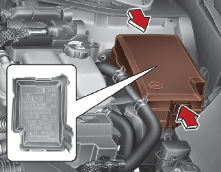
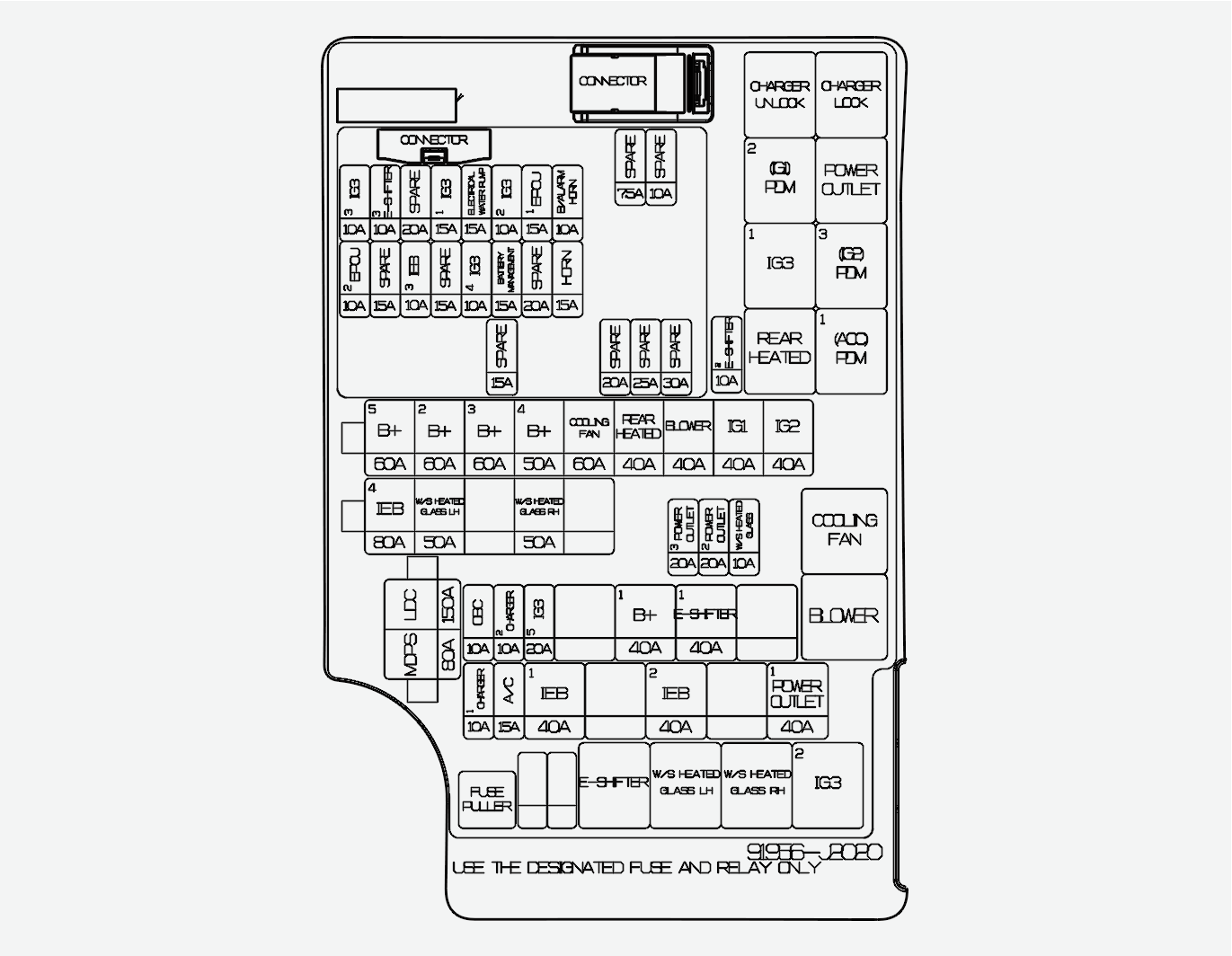
Refer to the following table for a description of the fuse.
|
Fuse Name |
Fuse rating |
Circuit Protected |
|
|---|---|---|---|
|
MUTL FUSE |
LDC |
150 A |
Fuse: POWER OUTLET1, IEB1, IEB2, CHARGER1, Air Conditioner, EPCU |
|
MDPS *1 |
80 A |
MDPS (Motor Driven Power Steering) Unit |
|
|
B+5 |
60 A |
PCB Block (Main Relay, Fuse: BATTERY MANAGEMENT, HORN, EPCU1) |
|
|
B+2 |
60 A |
ICU Junction Block (IPS (Instrument Panel Module) Control Module, IPS (Instrument Panel Module)(1CH)) |
|
|
B+3 |
60 A |
ICU Junction Block (IPS (Instrument Panel Module) Control Module) |
|
|
B+4 |
50 A |
ICU Junction Block (Fuse: TAIL GATE OPEN, SUNROOF, Amplifier, P/WINDOW LH, P/WINDOW RH, S/HEATER FRT, P/SEAT (PASS), P/SEAT (DRV)) |
|
|
COOLING FAN |
60 A |
Cooling Fan Relay |
|
|
REAR HEATED |
40 A |
Rear Heated Relay |
|
|
BLOWER |
40 A |
Blower Relay |
|
|
IG1 |
40 A |
PDM (IG1) #2 Relay, PDM (ACC) #1 Relay |
|
|
IG2 |
40 A |
PDM (IG2) #3 Relay |
|
|
IEB4 |
80 A |
Integrated Mobis Electronic Brake Control Module (Motor) |
|
|
W/S HEATED GLASS LH |
50 A |
W/S Heated Glass LH Relay |
|
|
W/S HEATED GLASS RH |
50 A |
W/S Heated Glass RH Relay |
|
|
FUSE |
POWER OUTLET3 |
20 A |
Front USB Charger |
|
POWER OUTLET2 |
20 A |
Rear Power Outlet |
|
|
OBC |
10 A |
OBC (On-Board Charger) |
|
|
CHARGER2 |
10 A |
Charger Lock Relay, Charger Unlock Relay |
|
|
IG3 5 |
20 A |
IG3 2 Relay, IG3 1 Relay |
|
|
B+1 |
40 A |
Long Term Load Latch Relay, ICU Junction Block (Fuse: DOOR LOCK, S/HEATER RR, BRAKE SWITCH, IBU (Integrated Body Control Unit)1, AIR BAG2, MODULE1) |
|
|
E-SHIFTER1 |
40 A |
E-Shifter Relay, Fuse: E-SHIFTER2 |
|
|
CHARGER1 |
10 A |
Charge Door Module, CCM Unit |
|
|
A/C |
15 A |
Air Conditioner Control Module |
|
|
IEB1 |
40 A |
Multipurpose Check Connector, Integrated Mobis Electronic Brake Control Module |
|
|
IEB2 |
40 A |
Integrated Mobis Electronic Brake Control Module |
|
|
POWER OUTLET1 |
40 A |
Power Outlet Relay |
|
|
E-SHIFTER2 |
10 A |
SCU, Shift Select Switch (SBW) |
|
|
HORN |
15 A |
Horn Relay |
|
|
EPCU1 |
15 A |
EPCU |
|
|
IG3 2 |
10 A |
OBC (On-Board Charger), EPCU, Electronic Air Conditioner Compressor |
|
|
BATTERY MANAGEMENT |
15 A |
BMU |
|
|
ELECTRICAL WATER PUMP |
15 A |
Electronic Water Pump (BMS, ER) |
|
|
IG3 4 |
10 A |
Charger Door Module, Active Air Flap Unit, ICU Junction Block (IPS (Instrument Panel Module) Control Module), Instrument Cluster, Charger LAmplifier, Audio,A/V & Navigation Head Unit |
|
|
IG3 1 |
15 A |
E/R Junction Block (IG3 2 Relay, IG3 1 Relay) |
|
|
IEB3 |
10 A |
Multipurpose Check Connector, Data Link Connector, Integrated Mobis Electronic Brake Control Module |
|
|
E-SHIFTER3 |
10 A |
SCU |
|
|
IG3 3 |
10 A |
3Way Coolant Control Valve LH/RH, E/R Junction Block (Cooling Fan Relay, Blower Relay), Air Conditioner Control Module, CCM Unit, Air Conditioning PTC Heater |
|
|
IEB2 |
10 A |
EPCU |
|
*1: MDPS (Motor Driven Power Steering) is the same as EPS (Electric Power Steering).
Refer to the following table for the relay type.
|
Relay Name |
Type |
|---|---|
|
Charger Unlock Relay |
MICRO |
|
Charger Lock Relay |
MICRO |
|
PDM (IG1) 2 Relay |
MICRO |
|
Power Outlet Relay |
MICRO |
|
IG3 1 Relay |
MICRO |
|
PDM (IG2) 3 Relay |
MICRO |
|
Rear Heated Relay |
MICRO |
|
PDM (ACC) 1 Relay |
MICRO |
|
Cooling Fan Relay |
MINI |
|
Blower Relay |
MINI |
|
E-Shifter Relay |
MICRO |
|
W/S Heated Glass LH Relay |
MICRO |
|
W/S Heated Glass RH Relay |
MICRO |
|
IG3 2 Relay |
MICRO |
Battery terminal cover
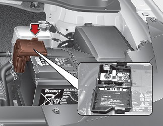
Not all fuse panel descriptions in this manual may be applicable to your vehicle. It is accurate at the time of printing. When you inspect the fuse panel in your vehicle, refer to the fuse panel label.